I was not sure if I should write this as a How-To guide or as a collection of
lessons learned. Having thought about it, I have decided to go the lessons
learned route. This means the read will be a sloppy mess and, perhaps, not
immediately useful. Hopefully, this is still a worthwhile endeavour.
The reason I decided to not do a How-To guide is because, ultimately, I
consider this project a ‘successful failure’. Therefore, I do not have the
confidence to write something as definitive as a How-To guide. Before I go
into why, though, I think I should explain what the project is.
Nicola Ellis asked me if I could create a 3D print
of Cave del Predil in Italy. I
said something along the lines of ‘I should be able to’ and got to work. The
goal was to use the print as part of an artwork she would exhibit at the
‘Peripheral
Memories’
exhibition (April 2021) in Italy's Friuli Venezia
Giulia region. I will not
go into too much detail on the exhibition here because it is out-of-scope for
this blog post. So, I have included a couple of extra links below if you would
like to know more about it.
I said above, the print is part of an artwork. One of the things Nicola did to
the print was coat it with mined zinc powder from the area. You can see the
result in figures 1 and 2 below.
 Figure 1: Finished version of the printed model, coated with zinc powder.
 Figure 2: Detail image of the printed model.
One of the things Nicola and I spoke about was the role of the 3D print. My
memory is a little fuzzy on this but my notes (I made at the time)
suggest there was talk about 3D printing a mould instead of a solid
structure. The mould would then be used to make a cast of the Cave del Predil
using the zinc powder situated there. So, I started looking into TPU
filaments
to print a flexible mould. Unfortunately, I had to scrap this idea in the end, because of how the 3D model was made.
I had a look on the World Wide Web to see if I could download a model of Cave
del Predil (fig. 3) and I found one at CG Trader; At least, I think I did. Neither Nicola nor I could work if this was Cave del Predil. So, we decided to keep this as a back-up if we could not improve on it. This is where the biggest breakthrough came.
 Figure 3: The CG Trader model.
I found the links below, which take 2D images and convert them to 3D. The
breakthrough came when we discovered we could use screen-capture recordings of Cave
del Predil via Google Earth.
Long story short, I could not get Autodesk Recap to work on my machine. My final
hunch was hovering around my graphics card being the thing it did not like. So,
I started to look for alternatives like it. On a personal note, I have come to
hate ReCap and will not recommend it. With that said, if it works for you, it
works for you. Moving on…
Having scouted around, I found my ReCap replacement: Agisoft's
Metashape. You can download Metashape
here.
After discovering Metashape, I found this
article
in Agisoft's Helpdesk Portal on how to reconstruct a 3D model using images. I
used this, in combination with the previous Instructables
Guide
and developed the following workflow:
- Create a screen recording (fig. 4) of the Cave del Predil area, using Google Earth.
- Create still-frames of the recording using FFmpeg.
- Import the still-frames into Metashape (fig. 5).
- Build a mesh from the still-frames (fig. 6).
Figure 4: Footage of Nicola scrolling around Cave del Predil in Google Earth.
To convert the screen recording into still-frames, I ran the following Bash
script.
bash
# cd into the directory with the screen recording in it.
ffmpeg -i predil-video-google-earth-001.mov -f image2 -vcodec copy \
-bsf h264_mp4toannexb "%d.h264"
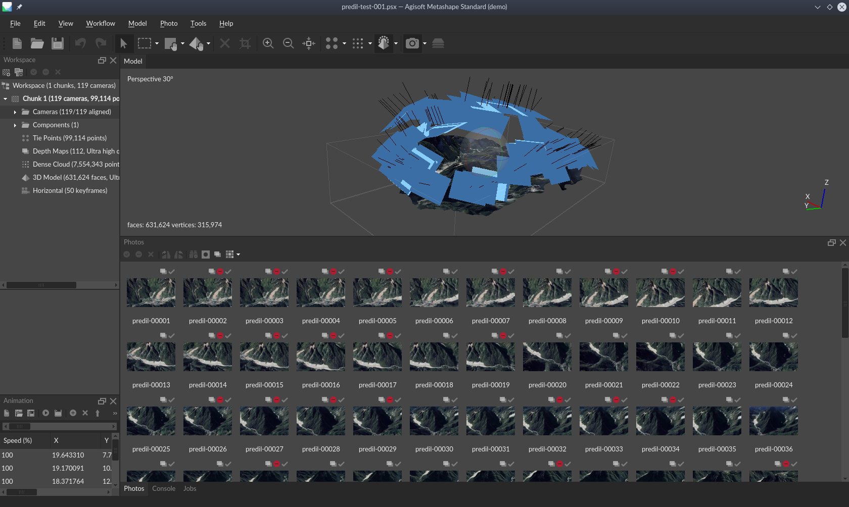 Figure 5: Still-frames and the mesh generated from the screen recording, in Metashape.
Figure 6: Video of the mesh created with Metashape.
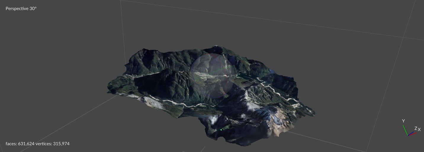 Figure 6a: Mesh of Cave del Predil (created with Metashape).
Apart from the ReCap problems, the project was coming along without too much
hassle. Having said that, it is here were things started becoming more
difficult.
When I tried to print any model made with Metashape, Ultimaker's
Cura – and
FreeCAD to be fair – would open them as a
mesh and not a solid shape. This lead to my 3D printer printing a ‘phantom
shape’. The nozzle would move as if it was actually printing something but
nothing came out of it. I think the main issue was the model did not have a
height/thickness. So, the printer would move the nozzle to the point where the
mesh was but, because it did not have a thickness to it, it did not print
anything. There was nothing to print, in other words. I will admit, though, I
could be wrong about this, but it is the best idea I have at the time of
writing. And, for the sake of completeness, I will note I found a guide on how
to create a solid from a
mesh
in FreeCAD, but it did not solve the problem. This was made even more weird when
I could get the printer to print the model's support structure – whilst the
actual mode did not print.
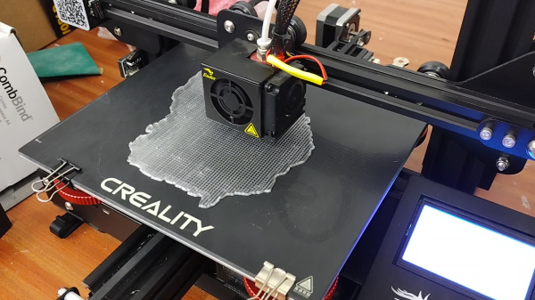 Figure 7: My 3D printer printing the support structures for one of the
Cave del Predil modes.
Figure 7: My 3D printer printing the support structures for one of the
Cave del Predil modes.
In an attempt to fix the ‘thickness problem’, I decided to import the mesh into Blender. From here, I managed to apply a level of thickness to the mesh (fig. 8), but I created a new concern in the process. A lot of debris, for lack of a better word, was
lurking over the now thickened mesh. Because of this, I had to remove the excess
polygons (fig. 9) manually, within Blender. Otherwise, Cura would not accept the
model.
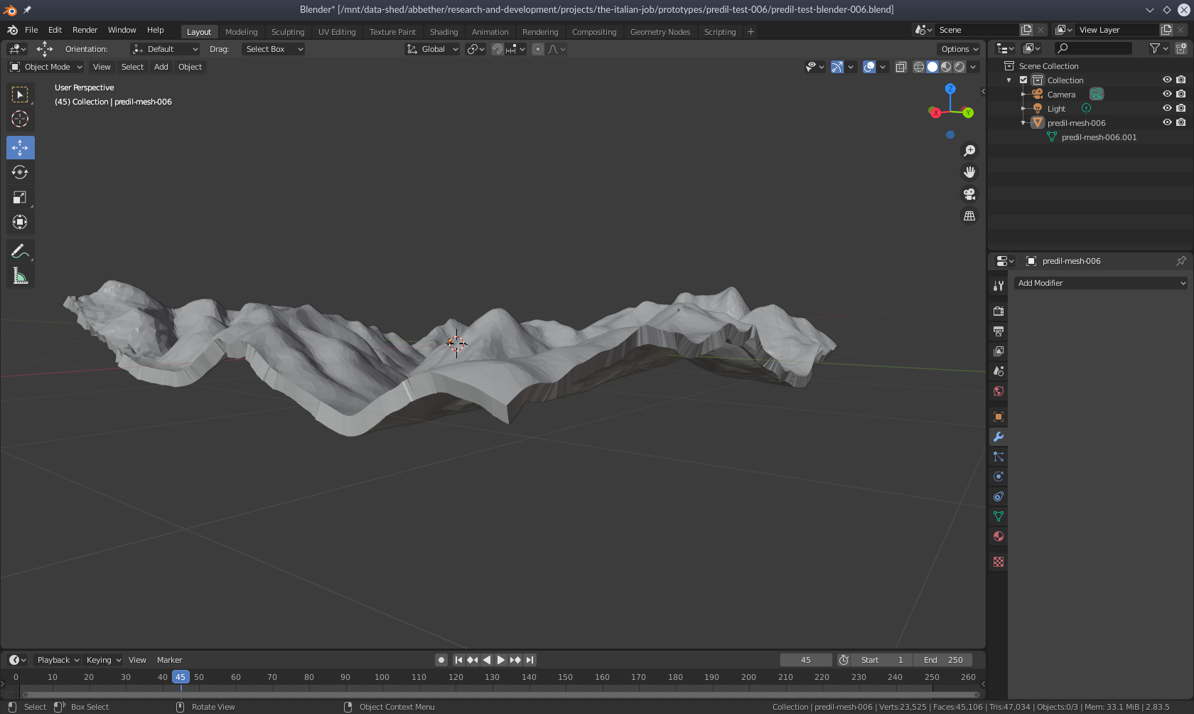 Figure 8: Blender allowed me to fill out the mesh (this is a ‘cleaned’ version
of the mesh/model).
Figure 8: Blender allowed me to fill out the mesh (this is a ‘cleaned’ version
of the mesh/model).
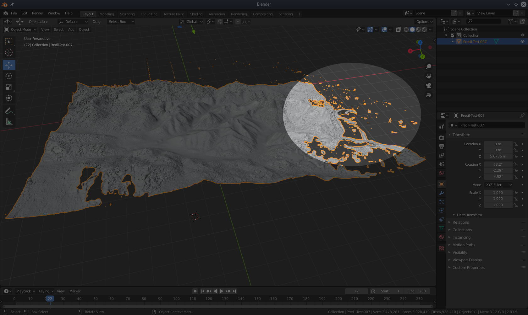 Figure 9: The mesh with excessive amounts of loose polygons which, needed removing.
I completed a few test prints using black Polylactic
acid
(PLA) after I removed the ‘debris’, and this new approach made a
difference. It actually printed, but it still relied on the support structures,
generated by Cura. The support structures were generated automatically, so it
was not an issue in my eyes. With that said, the aim of printing a mould was
completely out of the question now. After discussing this with Nicola, we
decided to try future prints with a transparent plastic, instead of the black
PLA I had used up to this point. The thinking at the time was it would minimise
the amount of colour-bleed through the zinc powder. I guess now is a good time
to confirm the plan had changed to coating the printed model in the zinc
powder. The end result turned out much better than I was expecting – as you can
see in the image (fig's 1 & 2) above.
The story does not end here, though. Several more problems still
persisted. The biggest one being the change to the transparent ‘glycol-modified’
Polyethylene
Terephthalate
(PETG). I do not know if I had a bad roll, my printer does not like transparent
PETG or (most likely) I missed something. Regardless, the PETG kept warping and
not sticking to the printer bed. I tried different supports (E.G. rafts),
temperatures (bed and nozzle) and layer thicknesses. The results did improve,
but I never resolved the issue completely. I tried printing in PLA again and the
result were much better – albeit in black. I, also, ran out of the PLA which
meant I was kinda stuck with the PETG – budget restraints and all that.
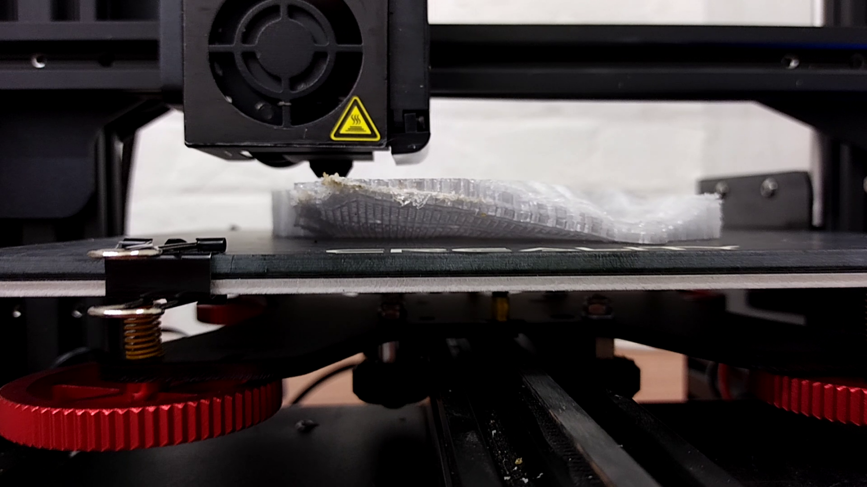 Figure 10: The PETG model warping and not sticking to the printer bed.
The next concern I needed to solve was how to increase the print’s rigidity. I never
truly solved this one, either. To be fair, I did actually increase it, but I
never got it to at a level I was happy with. My hunch is I increased the
scale of the model in Cura to a point which causes a similar effect to
pixelating a 2D rasterised image, such as .jpg and .png files. I tried
various scaling factors and could not find the threshold for where this rigidity
issue started to kick in. Each print, which was scaled up, had this problem,
though.
For whatever reason, Metashape produced relatively tiny models. Nicola wanted
the print to take up as much of the printer bed as possible and, to do that, I
had to scale the models up by 3000%. To put things into perspective, the printer
bed is approximately 22 × 22 cm. Even at 3000%, the print did not come close to
reaching the end of the bed. When I imported the Metashape meshes into Blender,
I needed to scale them by a factor of eighty before they were usable. Going from
Metashape to Blender and then Cura produced more rigid prints – with a smaller
percentage values needed in Cura – than going from Metashape straight to Cura.
Unfortunately, I do not have much documentation to share with you, regarding the
rigidity issues. I did not think to document the project’s progress which has
left me with very little to show you, visually speaking. On top of that, I no
longer have access to the failed models and prototypes. So, all I can do is try
to explain the problems as best I can.
Each up-scaled print had a sort of spongy feel to them. The prints felt like
their walls were connected by layers of elastic bands. They would squish inwards
but spring back, retaining their shape in the process. None of the models buckled
or broke, but that is mostly because I did not want to break them. I had, also,
ran out of PLA at this point. So, I could not prove it was the up-scaling or the
PETG causing of the issue – or the combination of the two. I have, since then,
printed other models with a different roll of PETG and not had the squishy feel,
so I am inclined to think it was the roll.
As stated previously, there was an intention to print a mould and create a cast
of it using the zinc powder from Cave del Predil. I thought this was doable when
I managed to give the Metashape mesh some thickness (in Blender). I was, also,
very optimistic at one point. It quickly died, though, after I realised fairly quickly
the model was too messy – for lack of a better word – to coax it into a form
useful for casting. The biggest hurdle I had to overcome here, before adding
‘walls’ to the model, was removing the loose polygons/faces (fig. 8). If you
tried to print the model with them part of the file/model, Cura could not slice
it or produce the G-Code necessary for
the printer to use. Unfortunately, cleaning the model up – after giving it a
thickness – was a manual, slow and tedious process. So, I did not have enough
time to work out how to extend the outer edges of the model and turn it into a
(box-shaped) mould (fig. 11). I did know how to get Cura to generate the support
structures underneath the model/mesh, though. This allowed Nicola to coat the print in
the zinc powder as an alternative solution. As stated previous, this was not the
original desire but this approach did generate the desired effect Nicola was
looking for (fig’s 1 & 2).
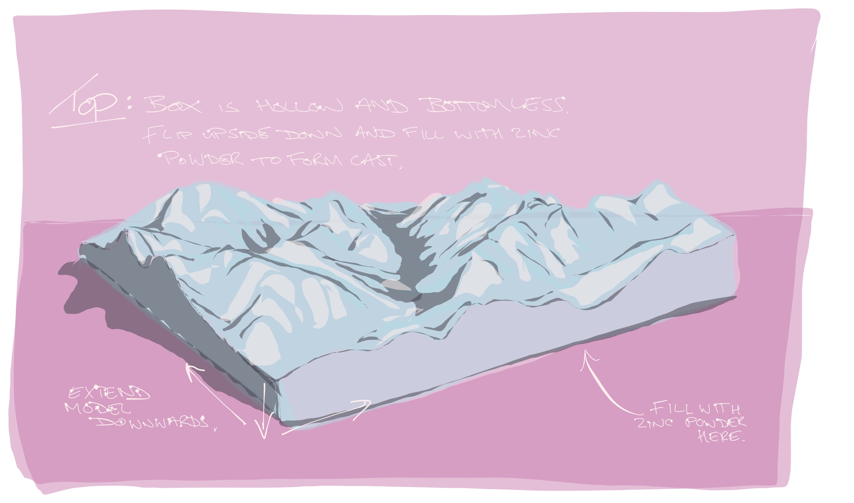 Figure 11: A sketch of how I wanted the mould to look.
You might have noticed the final result (fig. 1) is squared-off, while most of
the other images show a more organic perimeter. This ties into originally
wanting to create a mould. Whilst experimenting, using Blender's Boolean
Modifier
features, I could square-off the edges. Nicola decided to go with this design
decision because it allowed the models to use more of the print bed. Thus, I
could make the prints bigger (fig. 11).
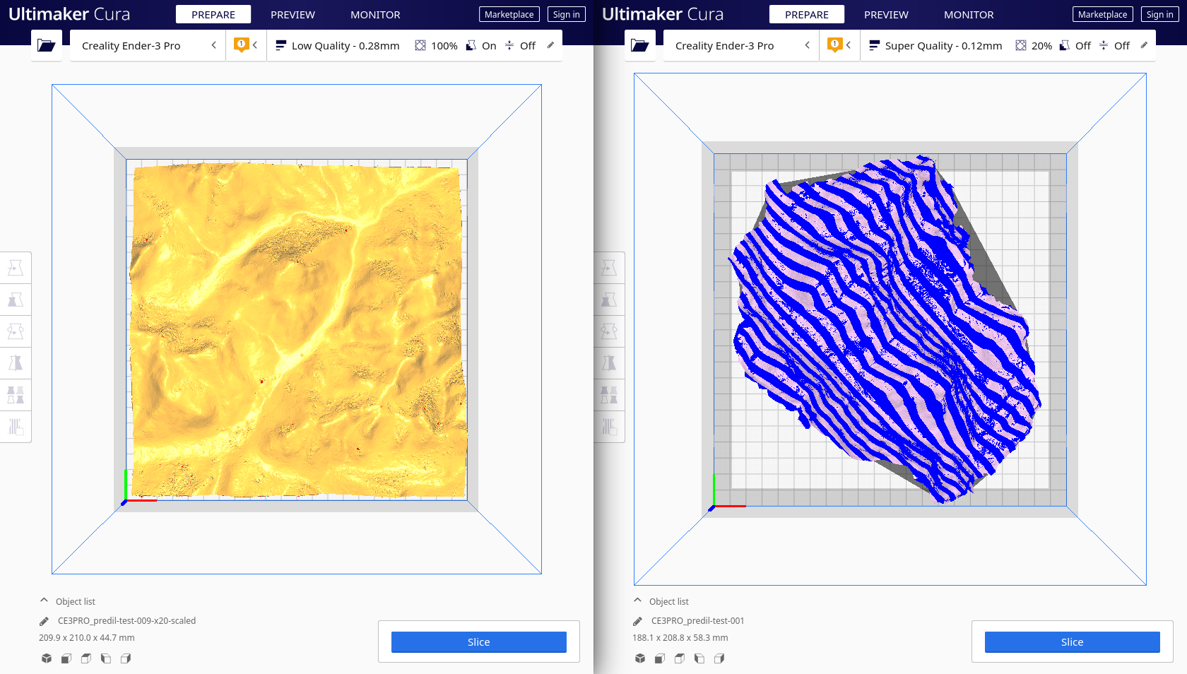 Figure 12: The organic models could not use as much of the print bed as the square models.
This last point is not really a problem. It is more of an observation, which I found
odd. After developing the system to produce a printed model from the video
footage, I began to increase the fidelity of the video output. This meant I
started recording the Google Earth footage of Cave del Predil for longer and at
higher resolutions. This, in-turn, increased the resolution of the screenshots
fed into Metashape. I, also, increased the settings in Metashape to produce more
detailed meshes. Having done that, I found the models did not improve. The video –
footage recorded at 720p produced prints equal to the footage recorded at
2K. For the purpose this project, it was deemed acceptable but I still found it curious. I sometimes ponder if
the lack of improvement is a natural by-product of this process, or it was
something I did wrong. If there was more time and money in the project’s budget,
I would have liked to investigate this more. Alas…
As I stated near the beginning of this blog post (or novella?), I view this
project as a ‘successful failure’ – from my point-of-view. From Nicola’s
point-of-view, the artwork has the effect and aesthetic she was aiming for. So,
I cannot say it is a ‘successful failure’ in that respect. Having got this far,
though, I hope you can see why I shied away from writing a How-To guide. My
hope is you take the lessons I learnt from this project, apply and expand upon
them without having to find out the hard way, like me.
To end this blog post, I will say I have made some renderings (with Blender) of
the digital model (fig. 13). You can view them in the 3D
Models section
here.
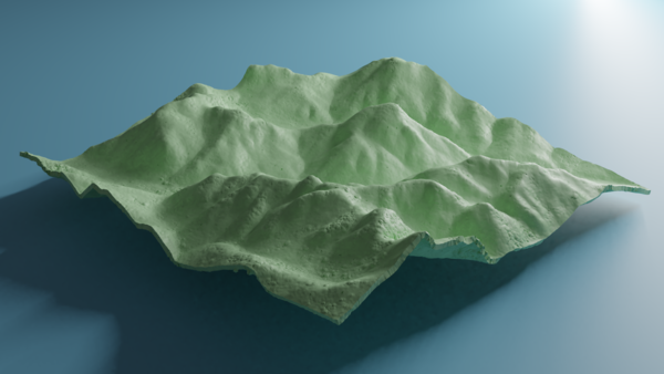 Figure 13: A digital model rendering of Cave del Predil.
�����������������������������������������������������������������������������������������
Figure 13: A digital model rendering of Cave del Predil.
�����������������������������������������������������������������������������������������